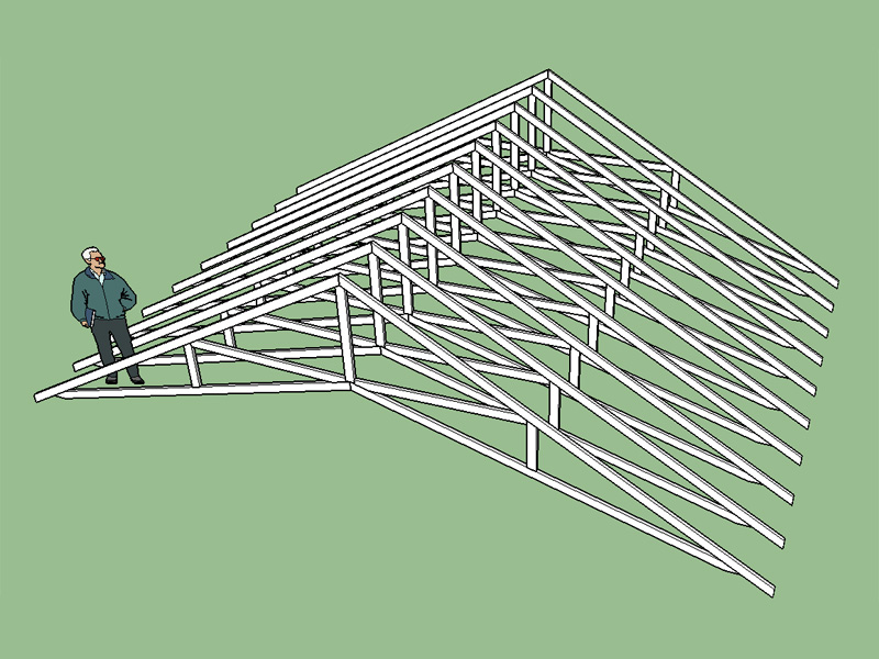
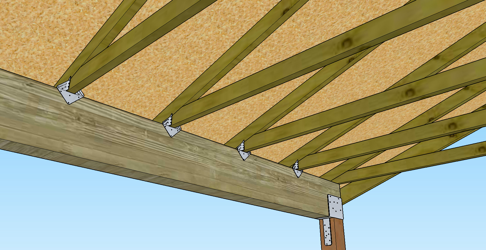
I was really hoping to get my hands on a a good truss software even if I had to shell out the big bucks. I contacted Miitek and Alpine and neither of them are willing to sell or lease their software to an architect or engineer. Something about trusses becoming a commodity. Bottom line is there aren't a whole lot of decent truss calculators/designers out there. If you want a truss design you have to get a truss manufacturer to quote you on a job and generate the engineered plans.
So I purchased a couple of books and starting reading up on trusses and how they are manufactured and designed. I've still got a lot to learn but just today I started into programming a basic truss estimator:
http://design.medeek.com/calculator/calculator.pl
![Image]()
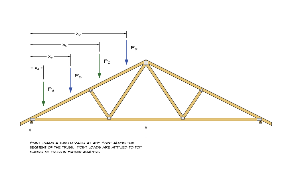
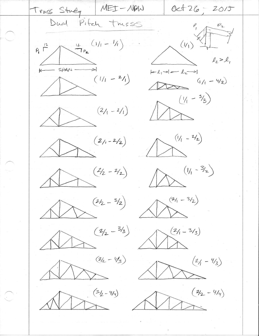
I've already added a few truss types, but the most complete to-date is the Fink truss which I have added all of the member analysis and deflections. I will be adding the plate analysis next and then duplicating this to the other truss types as time allows.
I apologize that Internet Explorer does not currently work with the images, for some reason there is no native SVG support in Microsoft browsers. However, there is a plugin you can install if IE is your browser of choice.
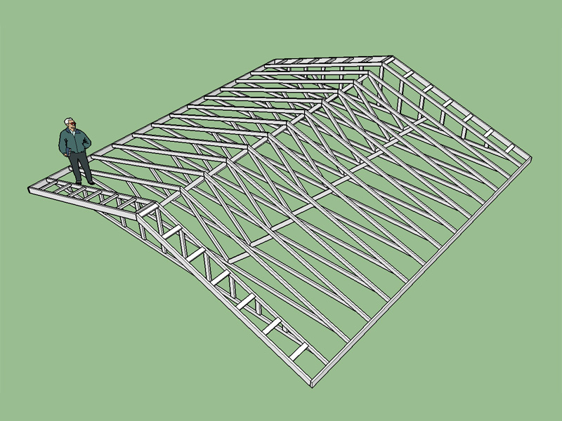
So I purchased a couple of books and starting reading up on trusses and how they are manufactured and designed. I've still got a lot to learn but just today I started into programming a basic truss estimator:
http://design.medeek.com/calculator/calculator.pl
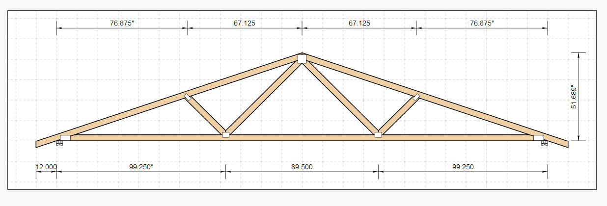
I've already added a few truss types, but the most complete to-date is the Fink truss which I have added all of the member analysis and deflections. I will be adding the plate analysis next and then duplicating this to the other truss types as time allows.
I apologize that Internet Explorer does not currently work with the images, for some reason there is no native SVG support in Microsoft browsers. However, there is a plugin you can install if IE is your browser of choice.

")