Contractor Talk - Professional Construction and Remodeling Forum banner
1 - 20 of 141 Posts

medeek

· Registered
Joined
·
137 Posts
Discussion starter · #1 ·
I was really hoping to get my hands on a a good truss software even if I had to shell out the big bucks. I contacted Miitek and Alpine and neither of them are willing to sell or lease their software to an architect or engineer. Something about trusses becoming a commodity. Bottom line is there aren't a whole lot of decent truss calculators/designers out there. If you want a truss design you have to get a truss manufacturer to quote you on a job and generate the engineered plans.

So I purchased a couple of books and starting reading up on trusses and how they are manufactured and designed. I've still got a lot to learn but just today I started into programming a basic truss estimator:

http://design.medeek.com/calculator/calculator.pl
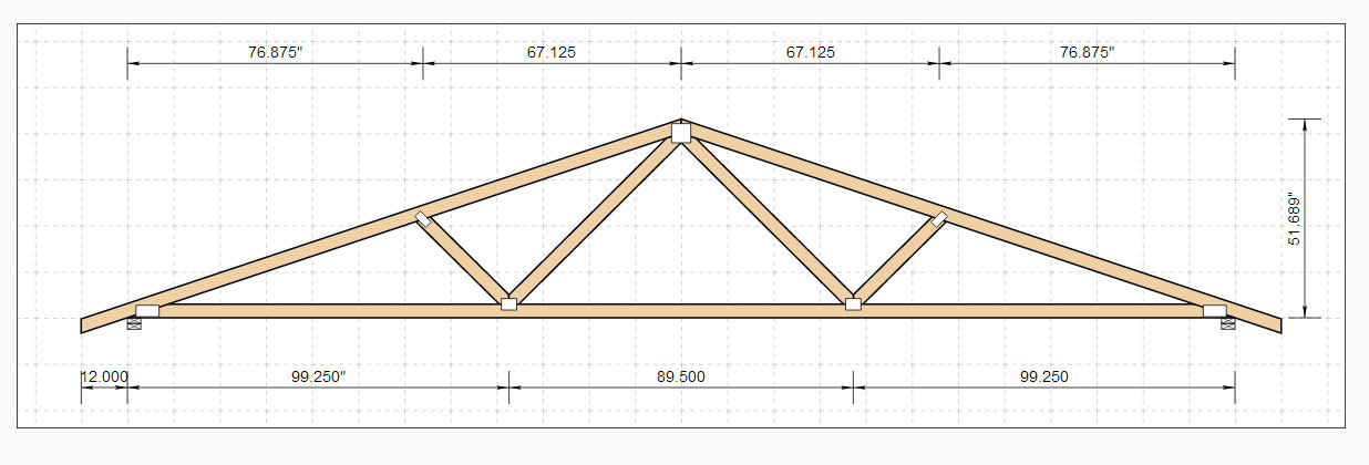
Image


I've already added a few truss types, but the most complete to-date is the Fink truss which I have added all of the member analysis and deflections. I will be adding the plate analysis next and then duplicating this to the other truss types as time allows.

I apologize that Internet Explorer does not currently work with the images, for some reason there is no native SVG support in Microsoft browsers. However, there is a plugin you can install if IE is your browser of choice.
 
I don't understand what you are trying to gain.

I call the Truss Yard and in a few minutes get a price.

If I need the calcs for plan check I just go pick them up.
Not sure what your program would be estimating. There is a great deal of spread in truss prices. Local guy is delivering 6 hours away and making money.
 
Discussion starter · #3 ·
Truss Design

And therein lies the problem.

The designing and engineering of trusses should not be controlled by "plate manufacturers" and "truss plants" it should be controlled by architects and engineers.

The plate manufacturers will only sell/lease their software to truss plants and not to licensed architects and engineers who could actually benefit from their software in the design and planning stages of many residential, commercial and agricultural structures.

I have given this some thought and the goal of this app in its final incarnation is the following:

This application is intended to be used primarily by Design Professionals (architects, engineers, etc.), Building Code Officials, Contractors and Inspectors with the goal of helping everyone that uses it to more easily understand the loads, parameters, calculations and limitations of a given common truss design. By changing geometry and loading parameters multiple design scenarios can be quickly compared and analyzed, hopefully providing a benefit to the design professional. However, let it be noted that this application is purely a tool to be used, similar in concept to that of a calculator or estimator.

In doing so I also hope to force the plate manufacturers to release a version of their software that is for use by architects and engineers.

I contacted both Alpine and Mitek a few months ago and was hoping to purchase or lease their software as I designed some new detached garages. Their answer to me was that they did not want their truss products becoming a commodity so they would not let anyone access their software except for authorized truss manufacturers who also purchased their plates.

The design of metal plated connected wood trusses in America is essentially a black box to most practicing engineers and architects.

I intend to change this.
 
I see from your web site that you are a Mechanical Engineer.
Do you have an in house SE to stamp your designs/plans? Maybe Washington is different.

So, if you were to design a project & used your Truss Design program, does it provide a cut list to the truss yard?

It seems if you take the design away from the Truss Yard you have introduced another player in the game which means another chance for error.

It would be curious to see if a Truss Yard would actually build your design or would they run it through their own program. Who would inspect/certify that the Truss Yard built exactly to your design. I wonder where the Truss Yard liability/guarantee would be using your method.
 
Griz I have a friend here that has opened and sold at least 4or 5 truss co. He is now an estimator for a big contractor and has builder ask him for truss design and the truss plant builds them.
 
... it should be controlled by architects.....

:laughing: oh HELL no! It would be the LAST group of people it should be controlled by.


... and engineers.
I think that they have enough on their plate.

It's a free (well sort of) market. You want to try changing it, go ahead.
 
Griz I have a friend here that has opened and sold at least 4or 5 truss co. He is now an estimator for a big contractor and has builder ask him for truss design and the truss plant builds them.
He probably has the truss software, no?
 
I think that whoever is fabricating the trusses should have control over the engineering. There are enough mistakes that happen with the way things are now. Adding another in the chain of command will just mean more errors. Our truss companies here work with builders and designers really well. They will even accept input from us framers on occasion. Many times I have submitted some crude sketches to see if an area can be trussed or not. I am sure that the engineers and architects do the same thing.
 
A calculator would be convenient, but anyone with the background can analyze a truss design, like you're doing. I don't see why any FEM software couldn't be used to do the analysis on a computer - maybe I'm missing something.

I'm not interested in specifying a truss design - it doesn't save me money and it shifts liability on to me.
 
Discussion starter · #10 ·
Wow, a lot more responses to this than I expected.

I understand that many architects, designers and even engineers don't really care to know what goes on inside the blackbox of truss design, I can respect that. However, there are situations where a tool like this could be useful for a designer and even though that designer may not spec out the truss fully on his plans and probably shouldn't, sometimes it would be nice to do a quick check to see if a certain truss design will fit an application.

For example I recently designed a detached garage with attic trusses. Some of the things that affected my design directly via the truss design were: overhang thickness (2x4 vs. 2x6), bottom chord depth, 3ply vs. 2 ply girder trusses, top chord depth.
 
The plate manufacturer's software isn't "truss engineering software", it's "truss design with our brand of plates" software. For liability and quality and reliability and reputation reasons, I can't imagine a plate manufacturer licensing that software to anyone but a truss maker certified by them, or an engineer like DWB's friend, who has a track record to trust.

As a contractor, I don't want to pay my engineer to design trusses - he has plenty of other work to do, and the truss company does the job just fine, given a set of requirements. Anyway, I don't think my engineer wants to design trusses, and I'm almost certain that every architect I've ever worked with, talked to, or passed on the street, doesn't want anything to do with it.
 
Discussion starter · #13 ·
I like the app hosted by jhu.edu, its actually quite fun to use. I've used it a number of times as a third party check on my statics calculations, so if definitely has its uses.

However, I'm looking for something that conforms to all the TPI standards and does the required calcs for lumber and deflections.
 
I may be missing something, but you’re an engineer and you don’t know truss analysis? Even if you’re not civil, didn’t you cover truss and beam analysis in your statics and mechanics of materials classes? To design the connectors and determine allowable stresses for material grades, look in NDS. To determine design loads, look in ASCE 7. You may want to consider briefly hiring a junior/senior college student in civil who took a wood structures design class to write a truss program for you in Excel. Pretty basic stuff. Good luck.
 
Discussion starter · #15 ·
I'm not talking about statically determinate truss analysis, I need the more in-depth stuff like matrix analysis (which I'm currently studying from my structural analysis book [Hibbeler]) and plate sizing based on the TPI 1 standard. Not something you get in your standard statics or mechanics of materials classes.
 
That makes more sense, though I think you’ll find that many common trusses are in fact determinate when you remove all of the zero-force members for analysis. You might also check out an old hand method for complex trusses I think called the 'method of substitute members'.

However, you’re certainly on the right track with the direct stiffness method (i.e. matrix analysis)—its great because, as you probably found out by now, its easy to program, requires no modification or change in procedure to solve determinate or indeterminate structures, and you really only have to deal with one general element type (frame element) that will handle axial force, moment, torsion, and shear effects. 3D coordinate transformations are somewhat cumbersome, though. This approach is the backbone of all modern structural analysis in structural engineering.

If you later want to go further into more complex stress analysis and move on to the finite element method, you’ll find that it uses the direct stiffness framework as well. I have read quite a few, and I think Hibbler’s coverage (though I’m sure I don't have the most current edition) of direct stiffness is fine. My guess is, however, you can find a number of free direct stiffness codes on the internet if you don't want to do the programming yourself.

If you have any questions about direct stiffness or FEA, let me know, I deal with these frequently and I'd be happy to help.

Good luck!
 
Discussion starter · #17 ·
Matrix Analysis

After about a good week of solid programming and scratching my head I've finally managed to add the requisite Matrix Analysis to my Truss Calculator. Thank-you R.C. Hibbeler for your Structural Analysis text on the subject (ch. 14 - 16), if the subject had not clearly laid out in front of me I would never have figured out the numerous steps to arrive at the solutions.

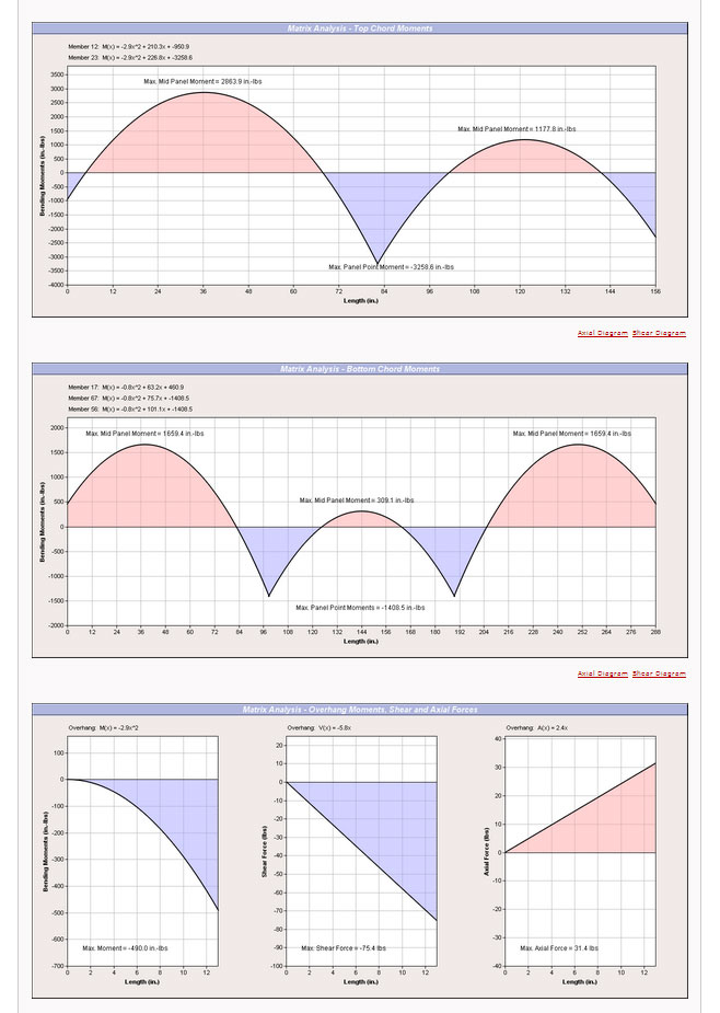
Here is an example of the output of my matrix analyzer for the Fink truss:

Image


I've even inserted the correct code to account for the additional loading/moments if there are overhangs. I double checked my work by modeling up identical trusses (beams and trusses members) in both Strand7 and Solidworks (COSMOS/Simulator). My result were within 1.5% or better, so I'm really happy about that.

My only concern with my analysis is how correct my analog for the truss really is. What I mean is that the bending moments are heavily influenced by the amount of rigidity of the joints. Fixing the joints (where chords meet) or pinning them dramatically affects the bending moments and even the axial and shear loads to some extent. My analog model is basically rigid at the heel and peak joints and pinned at all other web-to-chord or web-to-web joints. This seems to approximate most closely the moments calculated using the simplified method (pre TPI-2002).

What I also found quite interesting (and expected) is if you use a stronger type of lumber on the top chord as compared to the bottom chord. The top chord loads increase and the bottom chord loads decrease. The matrix analysis is almost as good as FEA. It's really quite cool to be able to calculate something like this just using a bunch of matrices.
 
Discussion starter · #18 ·
Leaving the peak joint as a rigid connection without exploring the implications of a pinned or semi-rigid joint seem like a cop-out to me so I spent most of the day attempting to release the peak joint so that it could act as a pinned (zero moment transfer) joint. For the web members I accomplished a similar task by altering the 6x6 stiffness (k') matrix so that it only included the axial terms, thereby eliminating any shear or moment forces, making these members axial only or simple pinned truss members. However, for the top chord members it was not such an easy task. I initially tried eliminating the row of the matrix that was responsible for the far end moments (pinned end), but it some became apparent that the interplay between moments and shear forces was more than I had originally thought. I was about to accept defeat but then after spending a couple more hours digging about online I came upon a gem of a paper published in 2010 in the Electronic Journal of Structural Engineering by M. E. Kartal. This paper outlined a couple of methods for obtaining the correct stiffness matrix for semi-rigid connections. With this information I was then able to add in feature so that one can select whether the peak joint is rigid, semi-rigid or pinned.

I then tested it for accuracy against an identical model in Solidworks Simulator for both the pinned and rigid connection at the peak joint with near perfect results. Unfortunately, Solidworks does not allow for adjusting the rigidity of connections between beams in its interface so I currently do not have the tools to test the accuracy of the semi-rigid model. However it appears to present the correct trends when compared against the other two options. If someone has a copy of ANSYS or some other reasonably high end FEA software I would be interested to see how well it will compare with third party verification.

A copy of the paper can be found here:

http://www.ejse.org/Archives/Fulltext/2010/2010v1/20103.pdf
 
Discussion starter · #19 · (Edited)
Modified Queen Truss Analysis

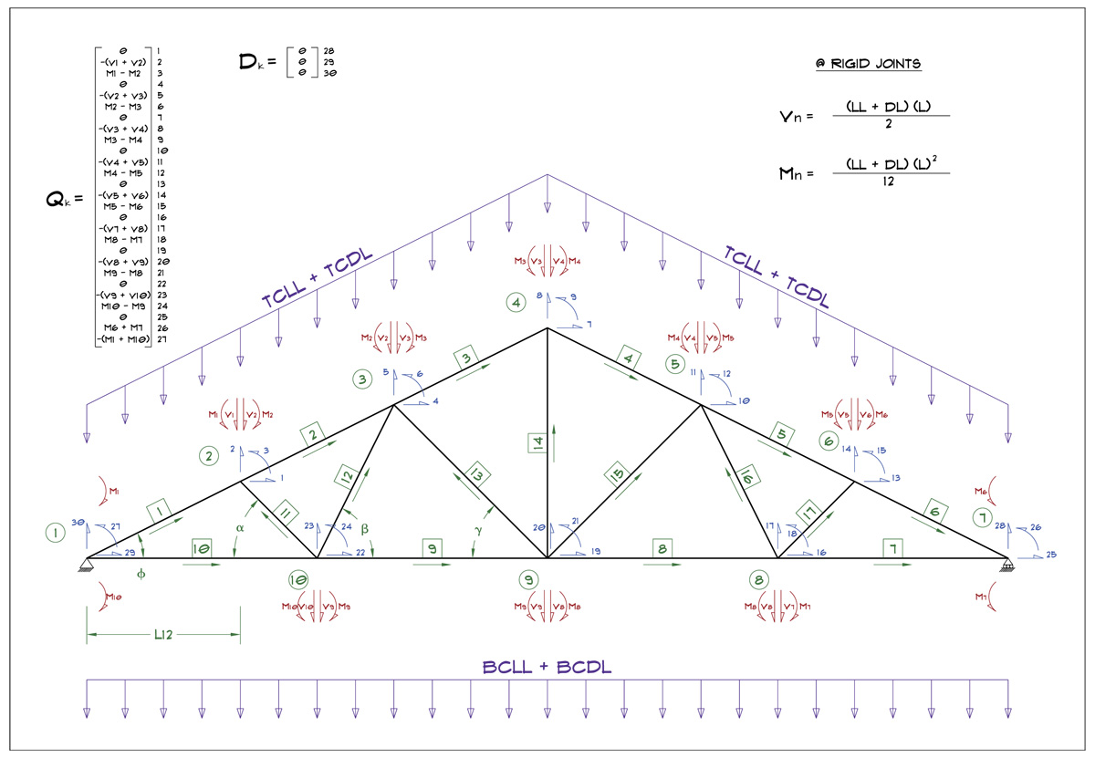
Starting to work on the modified queen truss, here is the schematic for the matrix analysis of it. The structure stiffness matrix will be a 30 x 30 matrix (900 values), its no wonder they didn't do this sort of thing prior to our modern computers, imagine trying to calculate this by hand. :)

Image


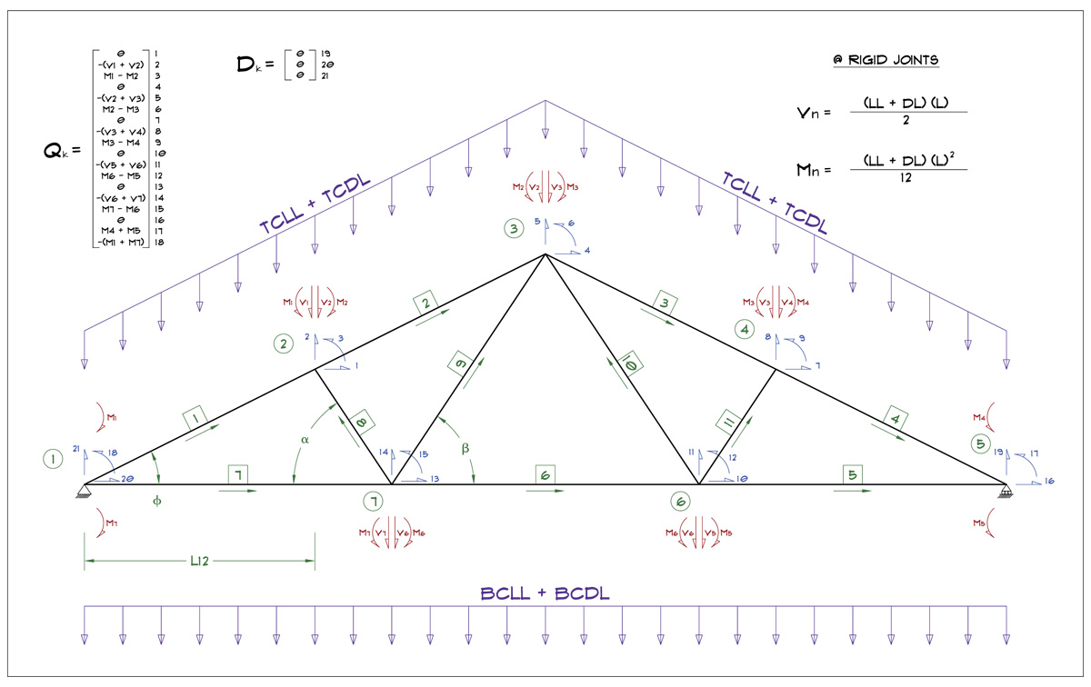
Compare this to the fink truss, which has a few less webs and hence the computations are less 21 x 21 matrix (441 values)

Image


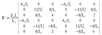
These schematics really say nothing about which members are pinned, semi-rigid or rigidly connected. The stiffness matrix (k) for each member is what determines that.

Image


In my analysis I am treating all of the webs as pinned jointed on both ends and only capable of transferring axial loads (classical truss members). The top and bottom chords at panel points are treated as rigid connections. The peak joint is treated either as rigid, pinnned or semi-rigid, this is user configurable. The heel joint is treated as rigid or semi-rigid. My reasoning and justification for these model settings is based on a number of papers I have compiled on the rigidity of joints of MPC wood trusses. I have saved each one and will compile a reference list at some point to accompany the truss designer documentation.

These two papers especially the bottom one were quite helpful:

http://design.medeek.com/resources/truss/DOCUMENTS/Paper_124.pdf

http://design.medeek.com/resources/truss/DOCUMENTS/20103.pdf
 
Discussion starter · #20 ·
Currently working on the plate calculations. Those will be rather lengthy but the upside is the summary is what most people will want or need, however I will show each lateral resistance, tension, shear, net section and moment check for each plated area of each joint. I'm doing one by hand first before I code it and I've already used 10 pages for the calculations and I still have to add the heel joint. I hope if nothing else people can use this app to at least better appreciate all of the checks that go into a simple truss.
 
1 - 20 of 141 Posts